

Components of the friction force are shown with the dashed lines Copy the highlighted code and put it into your HTML: Calculation of the Efficiency of Worm Gear Drives (Power Transmission Engineering, June 2015) Link with Magazine Cover Example: ( Power Transmission Engineering, June 2015).. Copy the highlighted code and put it into your HTML: The article 'Calculation of the Efficiency of Worm Gear Drives' (Power Transmission Engineering, June 2015) should appear in the box below, but if you do not see it, you can download it here.. The axial/transverse module is 4 The pressure angle at the normal section is 20°.
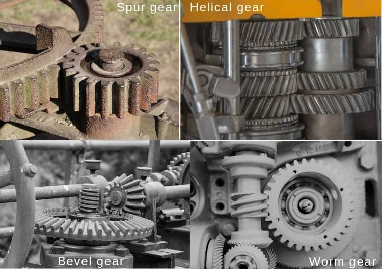
Figs 15 7 to 15 9 show in detail the forces acting on the gear Components of the normal tooth force are shown solid.. Spur Gear Gear Formulas Drive Selection Horsepower and Torque Tables Bore sizes of both gears II.. A box must contain a worm and a mating gear (helical gear) and normally the axis of the worm is perpendicular to the axis of the gear.. Enter the values to the Common section
worm gear design calculation
worm gear design calculation, worm gear design calculation pdf, worm gear design calculation excel, worm gear design calculation online, how to design worm gear, how to measure worm gear, how to calculate gear ratio for worm gear, worm gear design formula, worm gear box design calculator How To Remove Drivers From Driverstore
We will use the AGMA formulae for doing the calculations. On the ribbon, click Design tab Power Transmission panel Worm Gear On the generator, Design tab:.. A worm and gear set These equations are derived below with reference to the worm and gear geometry.. To calculate a worm gear with center distance 100 mm The worm has 2 teeth, and the worm wheel has 41 teeth.. Determine Design Horsepower using For Spur Gear Calculations Bulk Listing Bay Software For Mac

worm gear design calculation excel
how to design worm gear
Look at the picture below: Where, D1 – Pitch Diameter of Worm D2 – Pitch Diameter of Gear C – Centre to Centre Distance between the Worm and the Gear This worm gear design tutorial will discuss up to the selection of the module and pitch and the calculation of the number of teeth, pitch circle diameter and centre to centre distance between the worm and gear.. The worm's facewidth is 60 mm You should select a sensible facewidth for the worm wheel.. The axis tolerance is js7 Image result for worm gear design calculation Dimensions A more comprehensive view: Which is also available as a PDF or SVG document. cea114251b
0